


Part Two:
I made some mods to the carriage while I have it off. To install oiler ports, I drilled a stepped hole into each side of the carriage saddle.
(Click PIC to Enlarge)
I installed the 6mm push-button oilers and then tapped two 6-32 holes into the top of the saddle and put in some brass screws to act as studs to hold a rubber way protector for the rear of the saddle to compliment the front protector I made earlier (not shown).
(Click PIC to Enlarge)
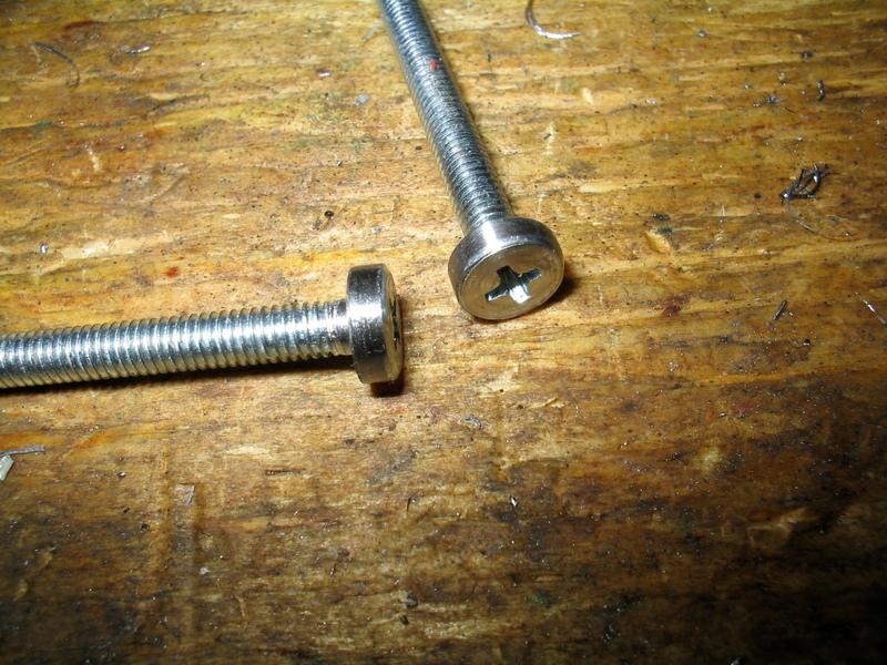
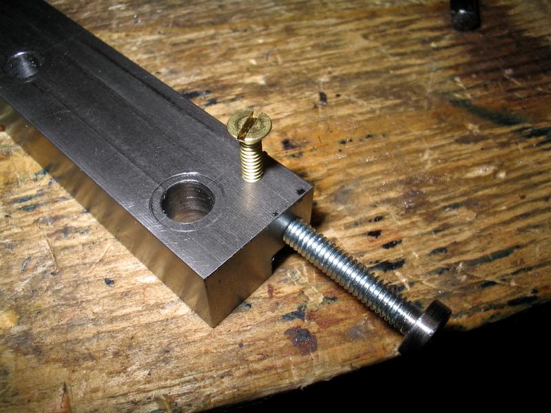
I made some adjustment screws to control gib position by shaping the heads of cap screws into cylinders on the lathe.
(Click PIC to Enlarge)
The brackets were drilled (clearance holes) for the 20mm M6x1 hex bolts that attach the gibs. (The original screws are too short, so you need to use 20mm replacements. I thought about counter-sinking the originals, but one one gib they would break through the side-wall of the bracket, so I dropped that idea.)
(Click PIC to Enlarge)
Here it's mocked up:
(Click PIC to Enlarge)
Next, I tapped and threaded some brass lock screws to lock the adjustment screws. (I used 4-40 b/c I had the taps & screws already and it's smaller diameter than the M4x0.7 gib screws)
(Click PIC to Enlarge)
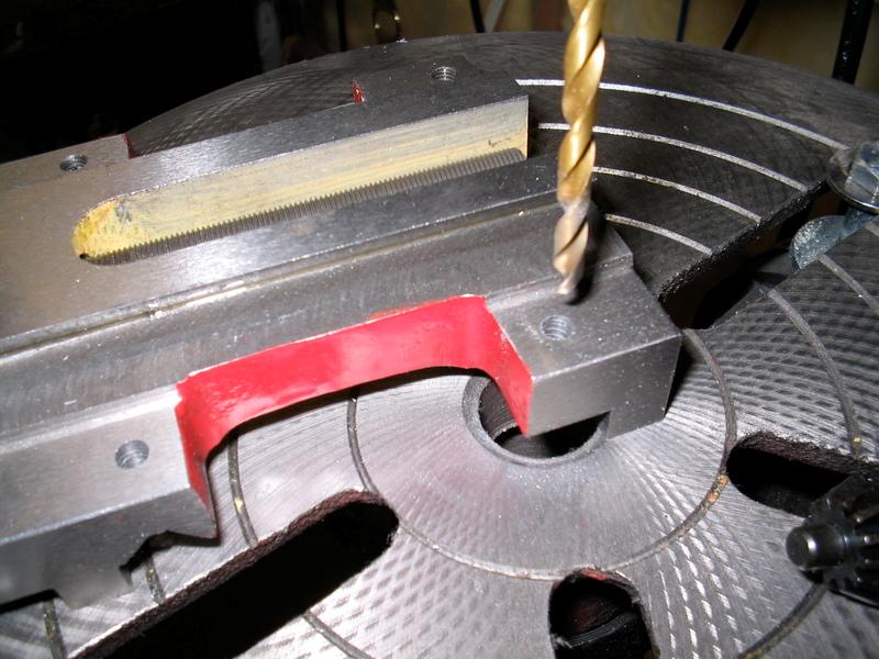
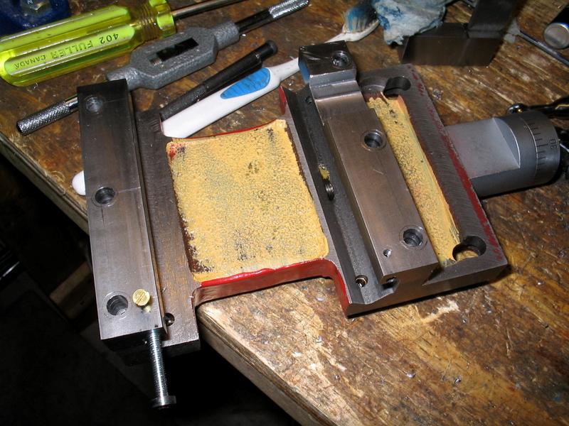
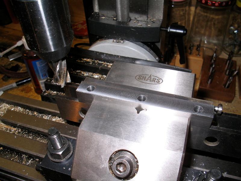
Here, the gib L-bracket clearance cut is milled for the apron spindle gear that engages the rack:
(Click PIC to Enlarge)
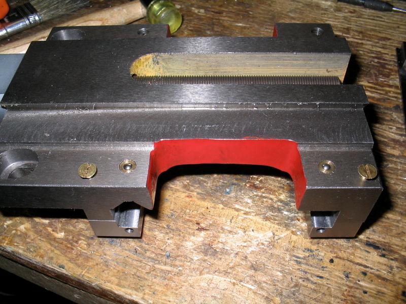
And here it is mocked up again.
(Click PIC to Enlarge)
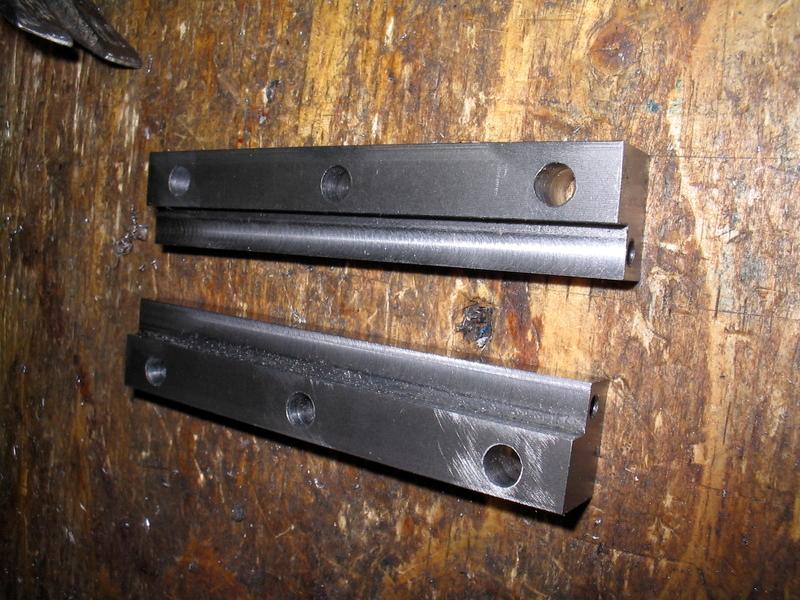
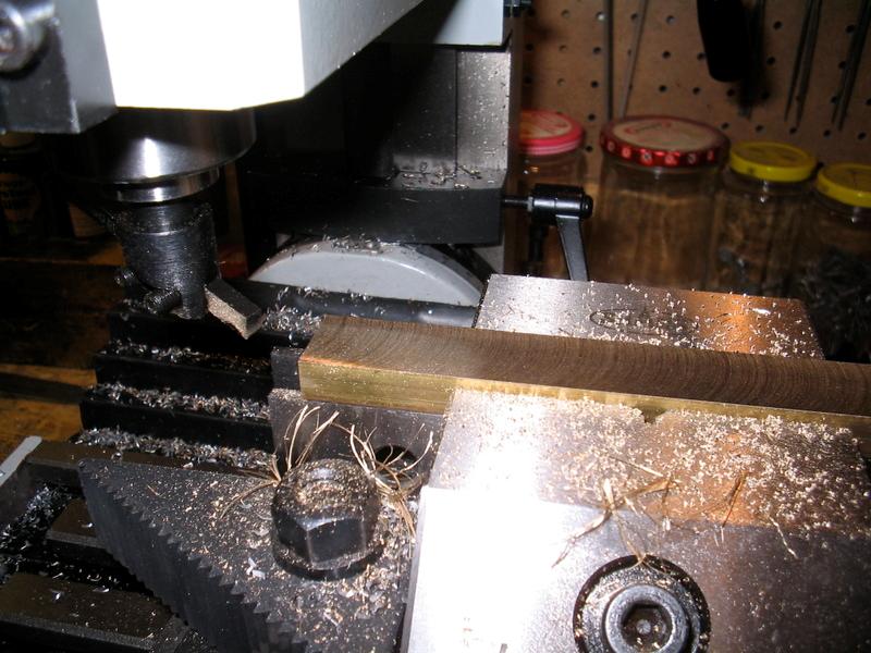
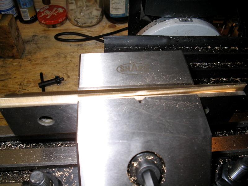
Making the gib strips from brass bar stock (brass is used as it is self-lubricating when friction-fit with steel or iron):
(Click PIC to Enlarge)
Some people dislike fly cutters, I think they are great in a mini-mill for doing surfacing and removing skin tension:
(Click PIC to Enlarge)
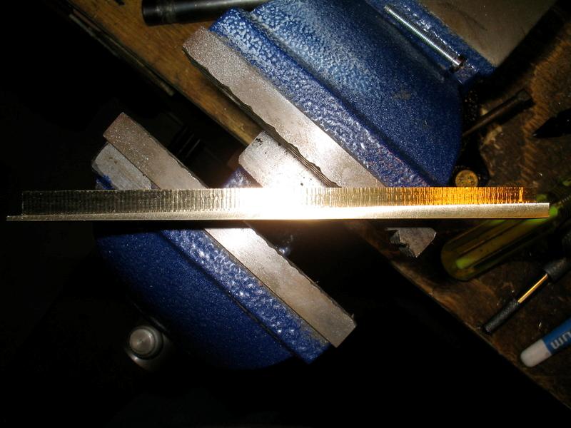
"dressed" stock, all squared up:
(Click PIC to Enlarge)
Basic shape milled into a bar:
(Click PIC to Enlarge)
Parted off in the bandsaw:
(Click PIC to Enlarge)
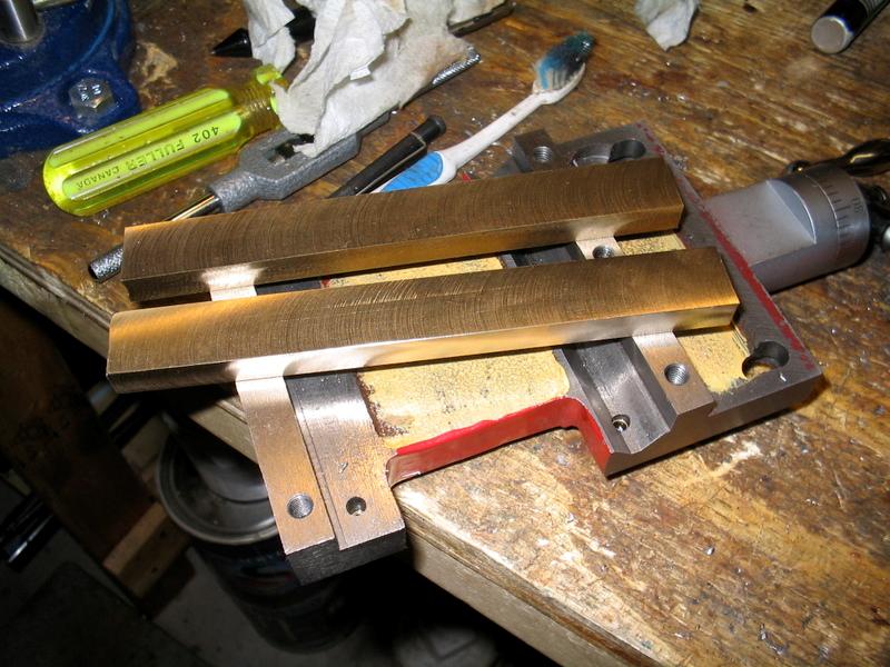
Both roughed out:
(Click PIC to Enlarge)
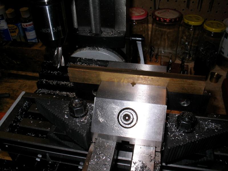
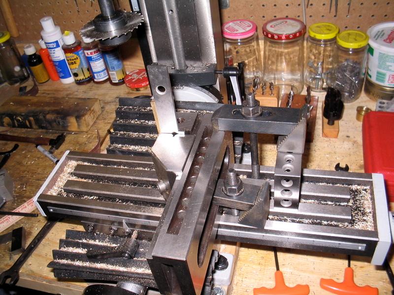
Look at this weird setup to cut the adjusting bolt slits. I didn't have a 3/32 end mill on hand, so I had to use a slitting saw. The extended gib strip is supported by a long parallel backed by a 1 degree angle plate and a HS tool bit spacer.
(Click PIC to Enlarge)
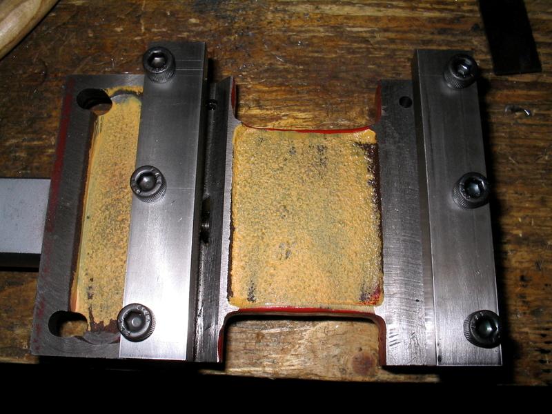
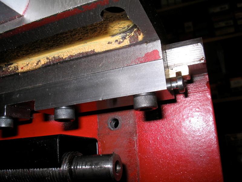
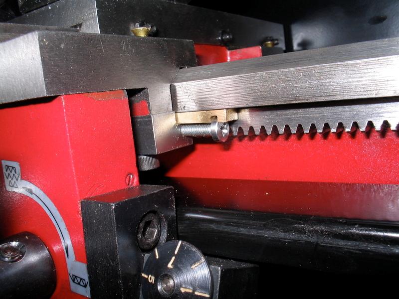
Here they are installed, but still binding up. My lathe bed was not perfectly parallel, top to bottom so I had to scrape and lightly file the underside edges. It now is near perfect. Also, I had never had the rack off the lathe bed. Glad I took it off as it was binding on the gibs. The bolt holes were never dressed at the factory, so burrs were catching the edges of the brass. I filed them off and took the opportunity to wire wheel off all the stray red paint. MUCH smoother now.
(Click PIC to Enlarge)
Hmm... didn't end up with much adjustment once he bed was scraped.
(Click PIC to Enlarge)
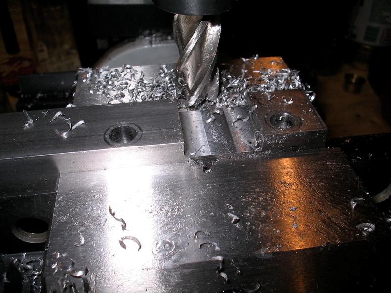
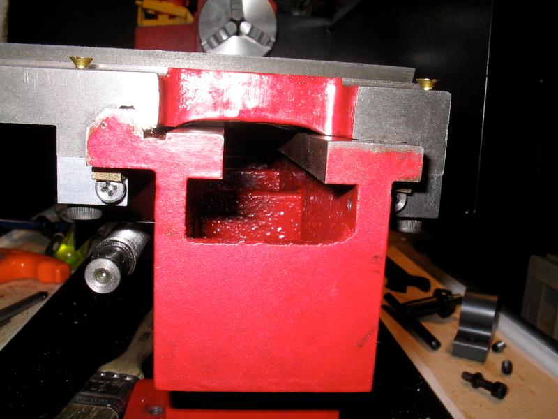
Solution, take about 5 thou off the top of each bracket:
(Click PIC to Enlarge)
Problem now was that the strips are now slightly too thick, so I took about 2 thou off them by superglueing them to the taper jig and milling them - much better:
(Click PIC to Enlarge)
The saddle and carriage assembly is now ROCK SOLID. WAY better than the stock gib plates. I'm really happy with this mod. Only thing I've now changed is I removed the lock screws. The adjustment screws aren't moving and the front side lock screw was hitting the pillow block bolt at the end of carriage travel whenever the threading wheel is not installed. I've removed them, but they can be re-installed if the adjustment screws start moving during use.
Now I'm going to upgrade the stock 3" lathe chuck to a 4" so I can get more workpiece capacity. The 3" is being retired to the rotary table permanently
Show of hands - did anyone here know Seig was ISO9001 certified for Quality control?
(Click PIC to Enlarge)
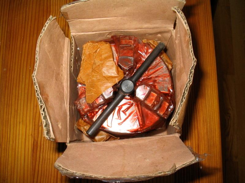
Now here is the new chuck. It's just like early Seig lathes - smeared in red grease goop.
(Click PIC to Enlarge)
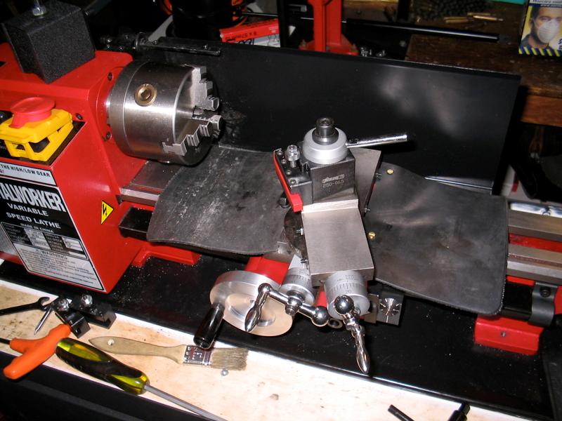
Got the rear rubber way protector/cover on too. I should also point out the quick-change tool post. This one is a "Phase II Hobby" model - I highly recommend it. Your tool shimming days will be OVER.
(Click PIC to Enlarge)
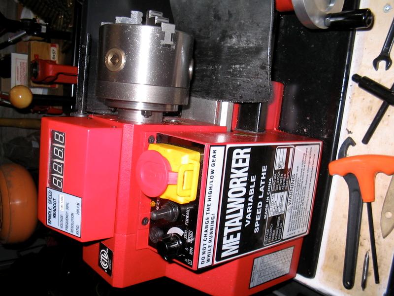
I also installed an LMS spindle RPM meter. It worked well, but I was NOT happy with this unit as-is. It was in the way of where I typically mount by magnetic-base DTI.
(Click PIC to Enlarge)
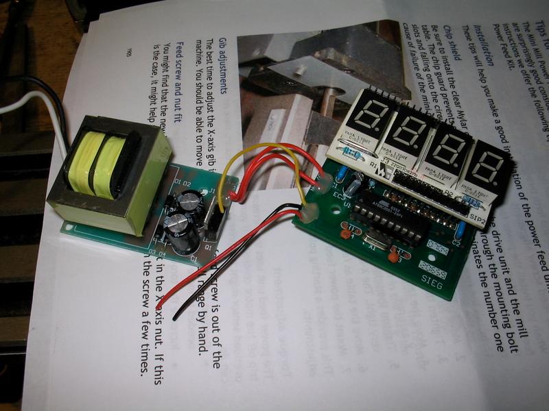
Here's the LMS DRO module:
(Click PIC to Enlarge)
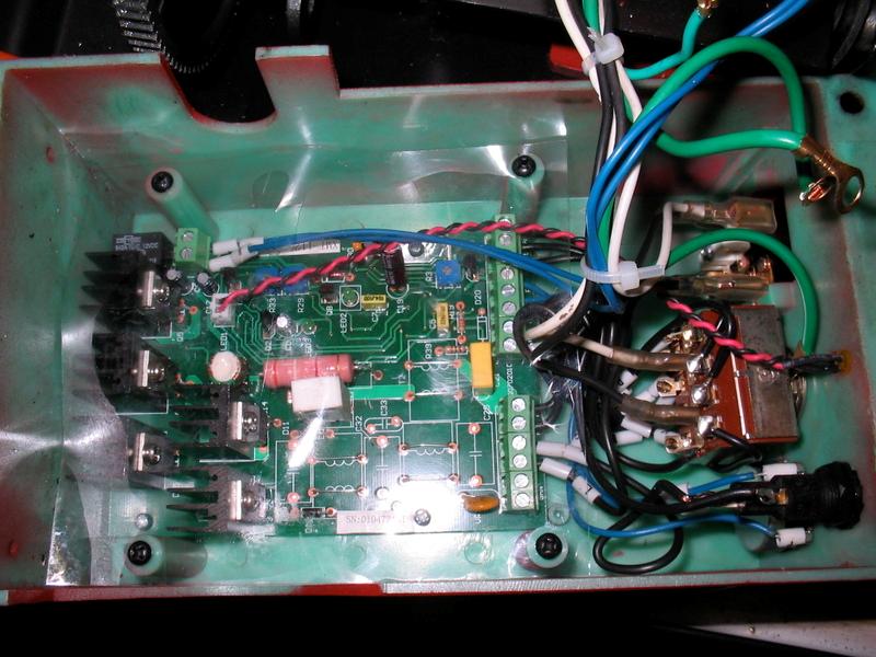
Inside the C2 electrical box (gonna be a tight fit):
(Click PIC to Enlarge)
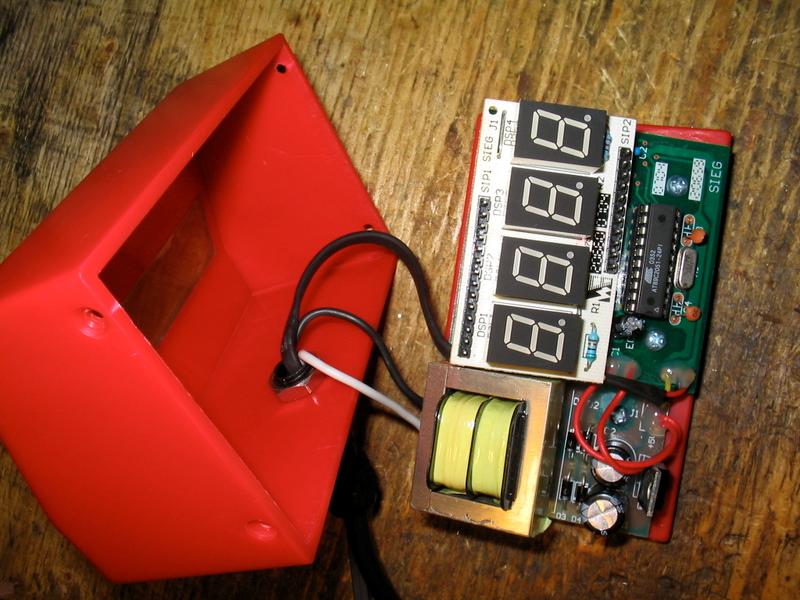
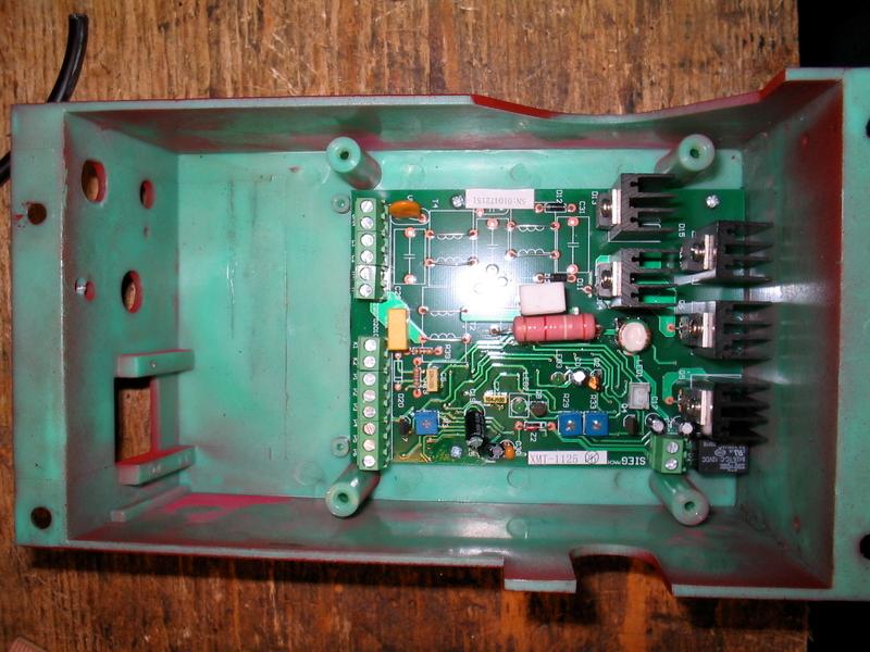
LMS module disassembled:
(Click PIC to Enlarge)
C2 box mostly gutted:
(Click PIC to Enlarge)
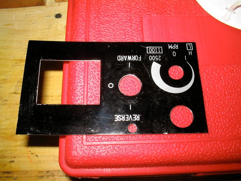
control label plate salvaged:
(Click PIC to Enlarge)
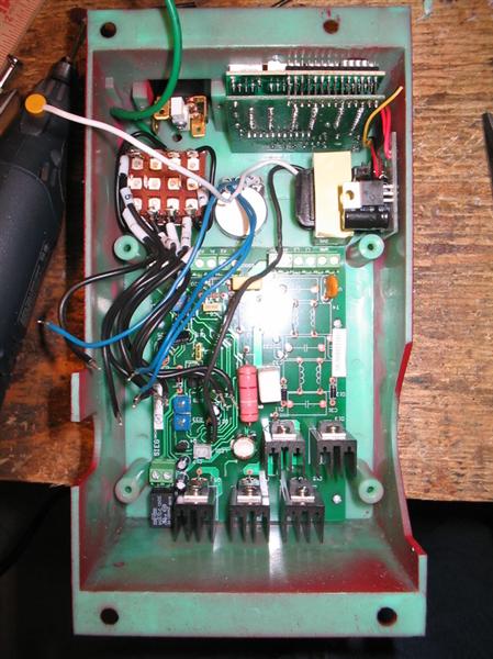
Here is the new layout for the inside of the control box mocked up:
(Click PIC to Enlarge)
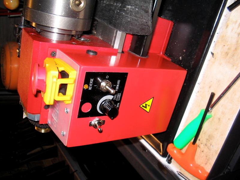
As you can see, the RPM meter will be where the old speed control and switch locations were on the top of the box. The transformer is mounted just below and to the right of the RPM readout. The switch and speed control are re-mounted to the front face of the control box and are located according to the old faceplate template. The emergency stop button will stay where it was.
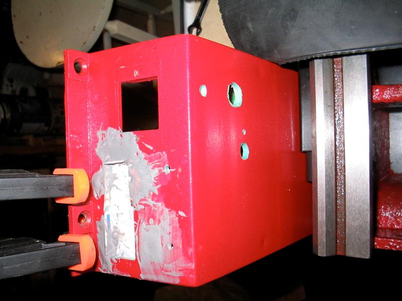
I need to make a plastic cover for the top of the control box to cover all the old holes. New holes have already been cut for the new component locations. The plastic top cover will have to have a plexi-glass window over the RPM readout.
I decided to fill the old holes with JB Weld. IAlso note I removed the "Metalworker" sticker from the front of the control box. I do not intend to re-install it.
(Click PIC to Enlarge)
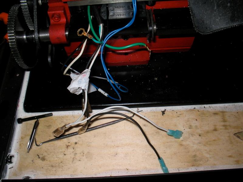
I then started some of the re-wiring. You have to solder some extensions onto the power wires leading off the 110v power supply. I used similar connectors to the others in the Seig lathe. These leads will power the small transformer for the RPM DRO. I will also be installing a toggle switch to power the DRO on and off.
(Click PIC to Enlarge)
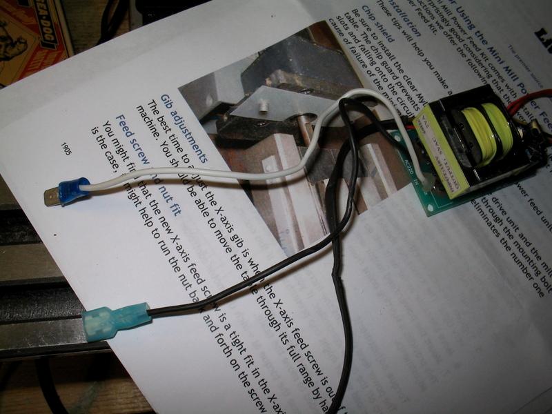
And here are similar connectors installed onto the transformer leads. This will allow the wires to be disconnected for disassembly, as opposed to if I had hard-soldered the wires in place.
(Click PIC to Enlarge)
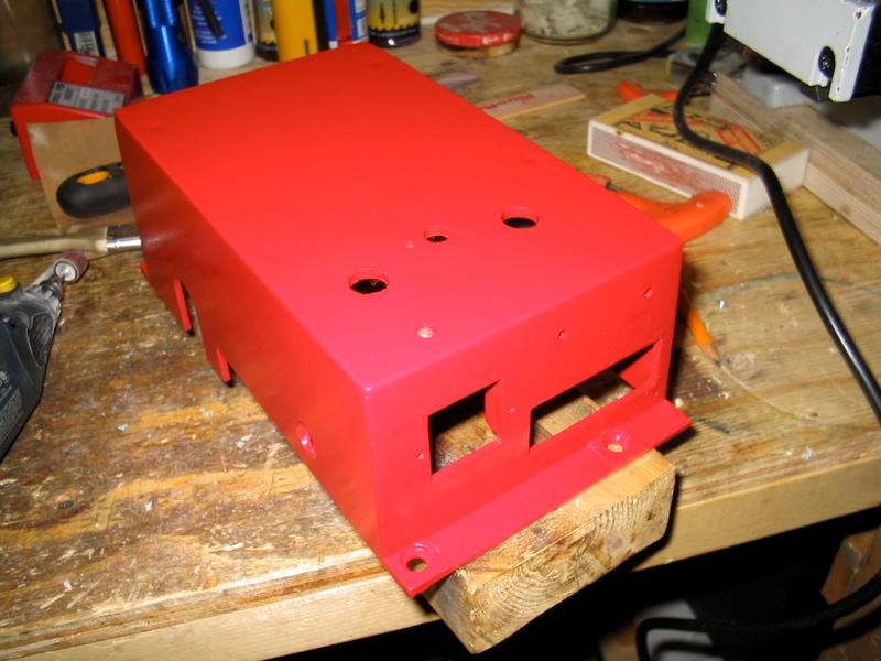
I got my control box cleaned up and re-painted. All the holes for the new hardware locations were drilled, the JB Weld patches were dressed and painted. I used Krylon plastic grade paint. It's not a perfect color match to the lathe, but it's close enough.
(Click PIC to Enlarge)
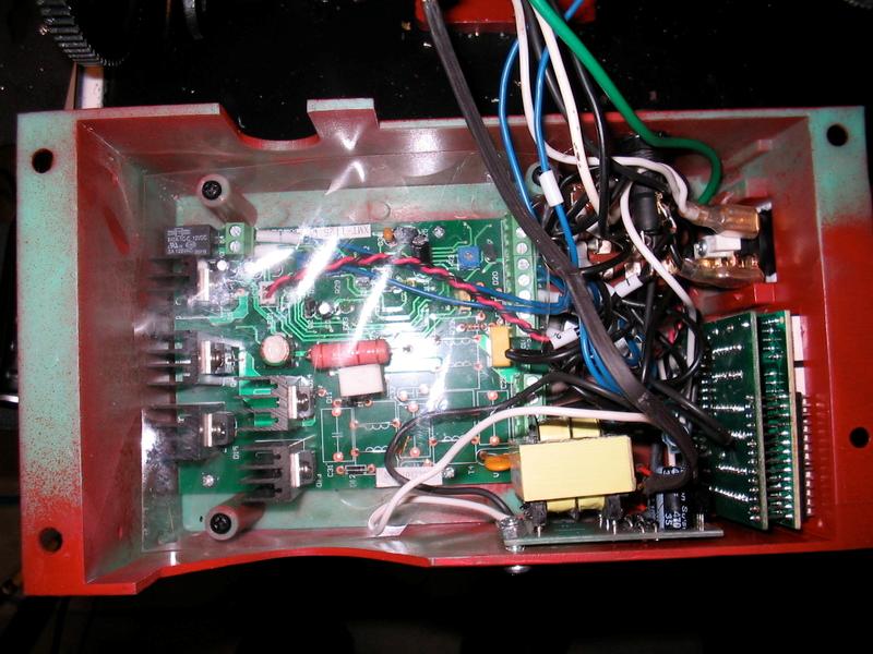
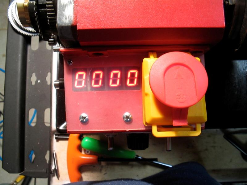
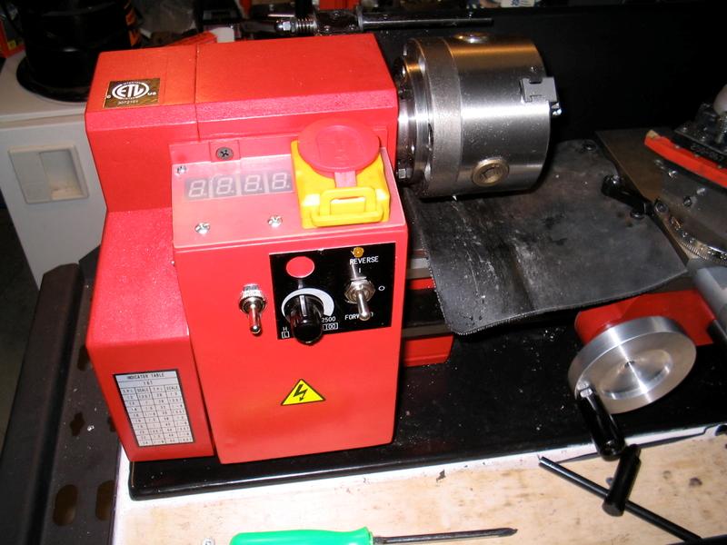
In this photo, the control box electronics are all mounted, wired, tested and the plastic ship shield re-installed. I had to remove one of the shield mounting posts to make everything fit (used a dremel abrasive wheel). I added a toggle switch to turn the DRO on and off, otherwise it would have been on all the time whenever the machine was plugged in. I also re-located the fuse port to the chuck-side of the control box.
(Click PIC to Enlarge)
This photo shows the selector gear housing being tapped for the sensor cable clips I made up from some bent sheet metal. These tapping fixtures are THE way to ensure your taps are straight and won't break. As always use cutting oil (this one is from LMS).
(Click PIC to Enlarge)
(Click PIC to Enlarge)
(Click PIC to Enlarge)
The spindle RPM DRO is not a necessary modification by any means, but it does help match cutting speeds from Machinery's Handbook (a MUST reference book) to the material you are cutting.
- Knowledge Library

- MKL Entry of the Month
- Australia
- Austro-Hungarian Empire
- Canada
- Czechoslovakia
- Denmark
- Finland
- France/Belgium
- Germany
- Italy
- Japan
- Norway
- Russia
- South America
- Sweden
- Switzerland
- Turkey
- United Kingdom
- United States
- Yugoslavia
- Is my rifle authentic or a fake?
- Jay Currah's Lee Enfield Web Site
- On-line Service Records (Canada)
- Technical Articles/Research
- Forum
- Classifieds
- What's New?
-
Photo Gallery
- Photo Gallery Options
- Photo Gallery Home
- Search Photo Gallery List
-
Photo Gallery Search
- Video Club
- iTrader


 PM
PM